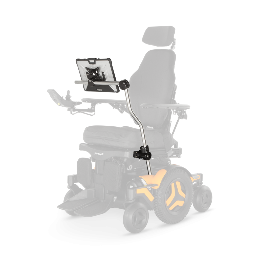
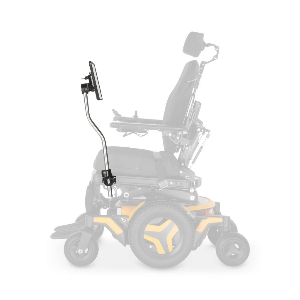
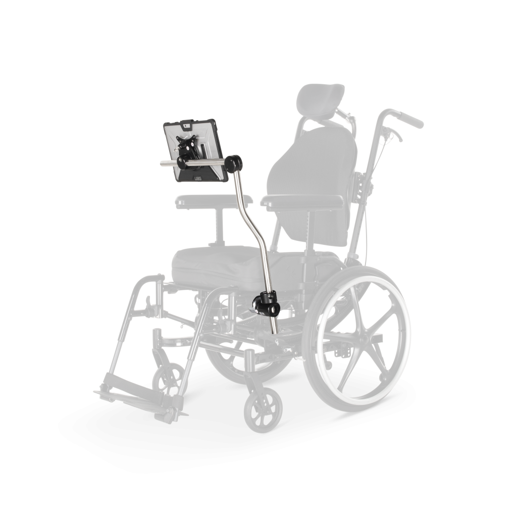
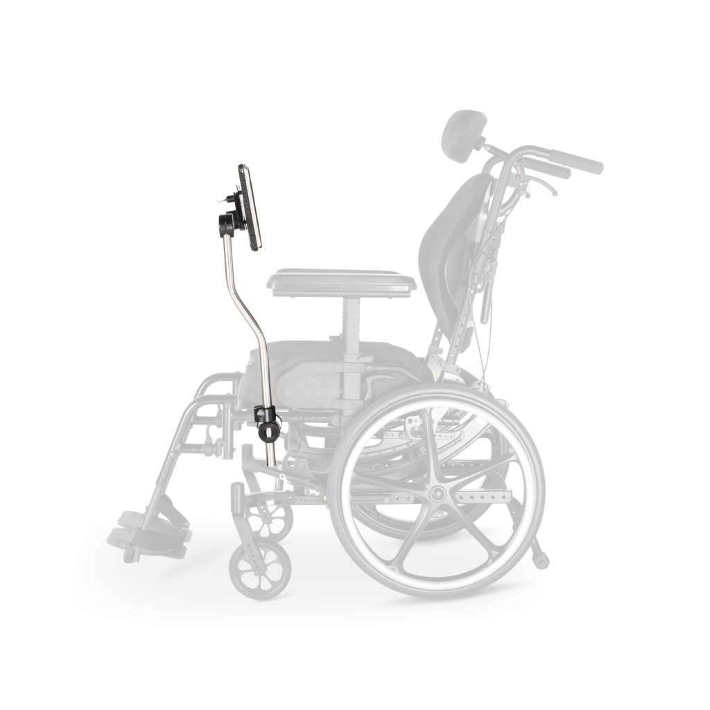
DAEDALUS TECHNOLOGIES, INC.
MAKING TECHNOLOGY MORE ACCESSIBLE
Installing the DAESSY Rigid Mount - DRM1, DRM1ROP and DRM1-BT
Steps in the Installation Procedure
- Identify the Parts
- Assemble and Install the Frame Clamp Components
- Install the Vertical Tube and Index Clamp (or ROP)
- Install the Tubing Connector and Horizontal Tube
- Install the Quick Release Base
Identify the Parts of the DAESSY Rigid Mount
The standard DAESSY Rigid Mount consists of the following parts:| Part Code | Part Name | DRM1 | DRM1ROP | DRM1-BT | DRM1ROP-BT |
| STR16 | Straight Tube - 16 " | ||||
| *S22x3 | S-bent Tube - 22 " with 3" offset | ||||
| RT22x16 | Right Angle Bent Tube | ||||
| TC90 | Tube Connector - 90º | ||||
| *TUSB | Total Quick Release Base | ||||
| *xxxIP | Frame Clamp Inner Piece | ||||
| UFCOP | Frame Clamp Outer Piece | ||||
| IC1 | Index Clamp | ||||
| RFCR | Removable Frame Clamp Receiver | ||||
| ROP | Removable Outer Piece | ||||
| DMSTools | Assembly Tools |
All the black anodized aluminum components have a part code stamped into the metal and these should be identified and laid out as shown in the picture. The Frame Clamp Inner Piece (UFCxxxxIP) may not be exactly as shown, and an Offset Link may be included. Bent-tube versions of the DAESSY Rigid Mount will have one Right-Angle tube in place of the Straight Tube, S-bend Tube and Tube Connector. ROP Versions of the DAESSY Rigid Mount will have a Removable Frame Clamp Receiver and Removable Outer Piece (RFCR-ROP) in place of the IC1 and UFCOP.
Caution
It is very important that all packaging be thoroughly inspected for loose parts and instruction papers. All the mount components must be identified and checked against the standard parts list, and the order list BEFORE any packaging is thrown away.
The Swivel Clamp for joining the UFCxxxxIP and UFCOP (or RFCR) is normally fastened into the axial hole of the UFCOP. Pinch Clamps for securing the tubes into the TUSB and IC1 (or ROP) are normally installed in their holes in the parts and retained by a plastic plug in the tube hole.
The parts shown in the figure are for a standard order. A customized mount may have different parts substituted.
Specific installation instructions may be supplied with components, especially components that vary from the standard parts list. In the case of contradictory instructions, component specific instructions provided with the mounting components will supersede the installation procedures outlined on these pages.
[Next Step: Assemble and Install the Frame Clamp Components]
Steps in the Installation Procedure
- Identify the Parts
- Assemble and Install the Frame Clamp Components
- Install the Vertical Tube and Index Clamp (or ROP)
- Install the Tubing Connector and Horizontal Tube
- Install the Quick Release Base
Rigid Mount