

Frame Clamp Assembly
Frame Clamp Assembly refers to the collection of components that are attached to the wheelchair frame and form the base support to hold a mount. The DAESSY Original Mounts and M-Series Mini Mounts use the same style of frame clamp assembly components. The DAESSY Lite Mount has a unique frame clamp; further information can be found under the Lite Mount section.
Frame Clamp Assembly refers to the collection of components that are attached to the wheelchair frame and form the base support to hold a mount. The DAESSY Original Mounts and M-Series Mini Mounts use the same style of frame clamp assembly components. The DAESSY Lite Mount has a unique frame clamp; further information can be found under the Lite Mount section.
Inner Pieces
Inner Pieces are available in a variety of sizes and styles to suit the frames of many wheelchairs. Clamp style inner pieces are used when frame bars are available on the main wheelchair frame or seat frame.
Learn More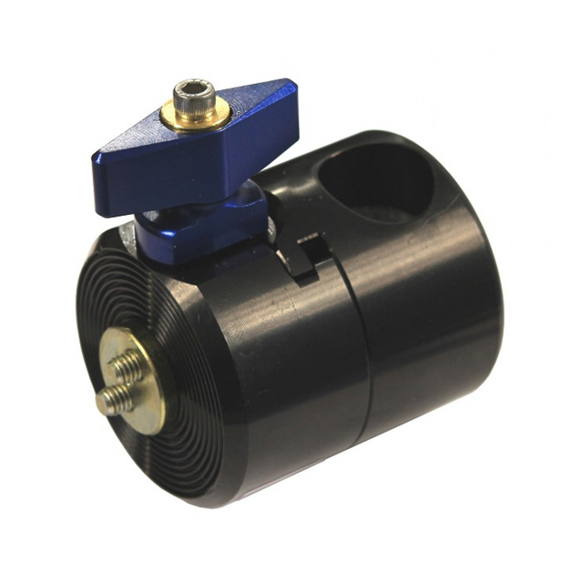
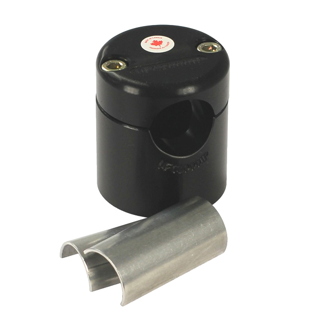
Outer Pieces + Receivers
The Outer Piece or Receiver supports the Side Vertical tube of a DAESSY Mount Assembly. The style of Outer Piece or Receiver is determined by the choice of mounting assembly.
Learn More