DAEDALUS TECHNOLOGIES, INC.
MAKING TECHNOLOGY MORE ACCESSIBLE

DAESSY Mounting System
Frame Clamps for Wheelchair Mounting


Connecting the Frame Clamp Components

In some straightforward applications of the DAESSY Rigid Mount and DAESSY Folding Mount it will be possible to connect the Frame Clamp Outer Piece directly to the Frame Clamp Inner Piece with one Swivel Clamp. However in many situations the Outer Piece will be displaced from the Frame Clamp Inner Piece location. This displacement may be necessary to:

Displacement or offset of the Outer Piece is achieved primarily with Offset Links and Frame Clamp Spacers. All DAESSY Frame Clamp components are designed for firm attachment at any angle with a system of grooved faces and Swivel Clamps.

A Note About Bolts

DAESSY Frame Clamp components are held together by standard 1/4"x20 UNC Socket Head Capscrews, commonly referred to as bolts. It is important that the correct length of bolt be used to connect components. If the bolts are too short there will be insufficient holding power, and the threads may shear within the bolthole. If the bolts are too long they may reach the bottom of the hole before tightening enough to hold the components firmly, or they may protrude excessively and interfere with other components, or the wheelchair itself.

Pinch Clamps are held with one 3/4" bolt. Swivel clamps are held with two 1" bolts. Most Frame Clamp Inner Pieces will have 1" bolts holding the cap and body together; Larger Inner Pieces may have longer bolts. Frame Clamps spacers will be supplied with longer bolts to substitute the standard Swivel Clamp bolts.

Frequently when a mount is being transferred or refitted to a new wheelchair the original bolts will be misplaced. Please Contact DAESSY for replacement bolts.


Grooved Face - IP end

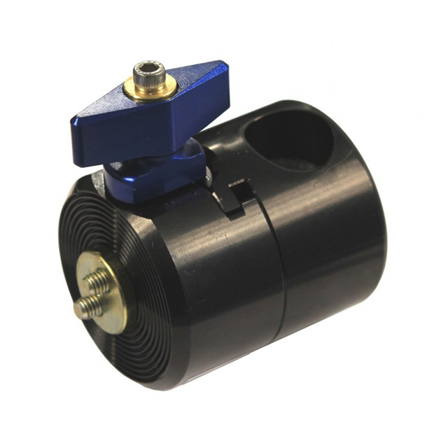
Circular Grooved Faces

The adjoining faces of all the parts for a Frame Clamp Assembly have circular grooves to give extra friction against movement when assembled. The grooves on an Inner Piece engage with the grooves on an Outer Piece but will not engage with the grooves on another Inner Piece. Offset Links and Frame Clamp Spacers have the letters IP stamped into the metal beside the grooves that attach to the Inner Piece and OP stamped into the metal beside the grooves that attach to the Outer Piece.


Caution:

All the grooved faces must be correctly matched and engaged before the Swivel Clamp bolts are tightened. When the grooved faces are correctly matched it will be possible to turn the mated components in a circle, but they will not slide across each other at the grooved face.


Swivel Clamps

Swivel Clamp

Swivel Clamps are used to connect parts of a Frame Clamp Assembly. The unthreaded head end of a Swivel Clamp has two 1/4" holes. The threaded end is also sometimes called the nut end of the Swivel Clamp and is threaded to receive two 1/4" UNC bolts. The standard bolt length provided with a Swivel Clamp is 1". The longer bolts needed to use the Swivel Clamp with a Frame Clamp Spacer (UFCSPCR) are supplied with the spacer. Always use the supplied Swivel Clamp bolts.

The threaded end of the Swivel Clamp should be engaged with a minimum of 4 full turns of each of the two bolts. The ends of the bolts should not protrude appreciably beyond the face of the Swivel Clamp nut end. Bolts should be tightened alternately to achieve the best grip.

In some cases it may be necessary to use the long arm of the 3/16" Allen Key to reach the heads of the Swivel Clamp bolts within the axial hole of the Frame Clamp Outer Piece. A Tommy Bar is provided to extend the short end of the Allen Key to allow sufficient torque to be applied. The Tommy Bar should not be used to extend the long arm of the 3/16" for tightening any bolts.


Offset Links

Offset Link (O3L)
Standard Offset Link – O3L

One Offset Link provides three inches of offset between the location of the Frame Clamp Inner Piece and the position of the Frame Clamp Outer Piece. In most cases the Offset Link can be set at any angle, thus the horizontal distance between the Inner Piece and the Outer Piece may be any measure between zero and 3 inches.

The grooved faces of the O3L are marked IP at one end and OP at the other. When two Offset Links are connected together, the IP end of one is attached to the OP end of the other. Each Offset Link is 1/2" thick and will move the Outer Piece this distance further away from the wheelchair attachment location of the Inner Piece.

One Offset Link is always used in the Frame Clamp Assembly of the Locking Swing Away Mount DLSA7 and provides the only method of front-to-back positioning of this mount and of attachment for the Inner and Outer Pieces. One Offset Link is always used on the Locking Rear Folding Adapter of the Lockable Rear Folding Mount DLRFM8 and provides the only method of attachment to the Frame Clamp Inner Piece. Additional Offset Links may be used with either mount assembly. Offset Links can also be used to obtain the correct position of the Rear Folding Adapter of the DRFM6 or Locking Rear Folding Adapter of the DLRFM8 to allow unobstructed rear folding motion.


Single Sided Offset Link – O3LS

The Single Sided Offset Link O3LS has the grooves for the Inner and Outer Pieces both on the same side. When the O3LS is used the Inner Piece is attached facing inwards towards the frame of the wheelchair and the Outer Piece is located directly in line with the Inner Piece and does not protrude as far as a standard Frame Clamp Assembly. Single Sided Offset Links may be used with the Lockable Rear Folding Mount DLRFM8 to position of the LRFA closer to the wheelchair.

Caution – Offset Link Angles:

Offset Links (O3L) and Single Sided Offset Links (O3LS) that display a Serial Number greater than #406000 may be connected at any angle provided the grooved faces are correctly matched and seated.

Any Offset Link or Single Sided Offset Link displaying a Serial Number less than #406000, or displaying no Serial Number, is an older design and is subject to limitations on the connection angle.

Two older design Offset Links must not be connected directly together at an angle less than 135º. An older design Offset Link must not be directly connected to a Rear Folding Adapter (RFA) at an angle less than 135º.

If a Frame Clamp Spacer (UFCSPCR) is installed between two older design Offset Links or between an older design Offset Link and an RFA, the components may be connected at any angle.

Frame Clamp Spacer (UFCSPCR)

Frame Clamp Spacer – UFCSPCR

The Frame Clamp Spacer (UFCSPCR) is 3/4" thick and a maximum of two Frame Clamp Spacers can be used to move an Outer Piece 1 1/2" further away from the wheelchair attachment locations. One side of the Frame Clamp Spacer has grooves to complement an Inner Piece and the other side to complement an Outer Piece. The Frame Clamp Spacer can be used in combination with the Offset Link (O3L).


Right 
Angle Spacer (UFC90)
Right Angle Spacer - UFC90

An additional spacer component is the Right Angle Spacer (UFC90) which provides a 90 degree change in the plane of the grooved faces of the Frame Clamp components. This is useful when the only available mounting location on the wheelchair is perpendicular to the side of the chair.


[GO TO: Top] | [GO TO: Frame Clamp Inner Pieces] | [GO TO: Frame Clamp Outer Pieces]
[DOWNLOAD This page in PDF format]

DAESSY Mounting System

Selecting a DAESSY Mount Assembly

Rigid Mount
DRM1

Folding Mount
DFM2

Locking Swing-Away Mount
DLSA7

Rear Folding Mount
DRFM6

Lockable Rear Folding Mount
DLRFM8

Positioner Mount
DPM9

Desk Mount & Clamp Desk Mount
DM & DMC

Rolling Mount
RM-24 & RM-32

More information on the DAESSY Mounting System

Catalog, Ordering and Prices

DAESSY Home

Copyright 2006